Maximum Power Tracking based Solar Charge Controller
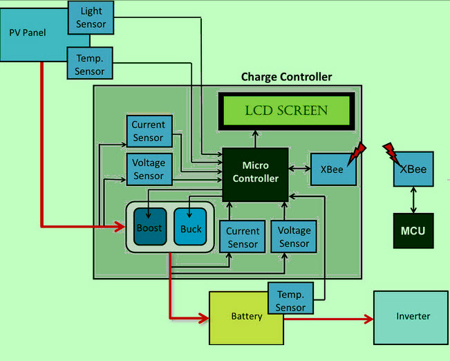
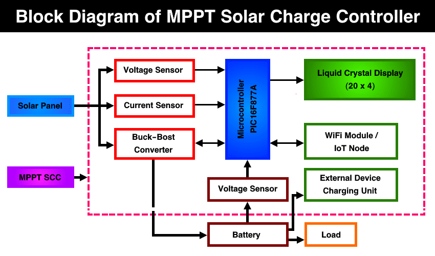
Arduino Source Code/Program. We can use Arduino IDE to write the MPPT Solar Charge Controller Project Code. The code has all the parameters and functions to measure Solar Panel Voltage, Current, Power, Battery Voltage, Charger state, SOC, PWM duty cycle, load status. The 20×4 LCD Display will show the real-time status of this parameters.

Connect Solar Panel to Charge Controller 3 Steps (w/ Videos
The solar charge controller (frequently referred to as the regulator) is identical to the standard battery charger, i.e., it controls the current flowing from the solar panel to the battery bank to prevent overcharging the batteries. As in a standard battery charger, it can accommodate different types of batteries.
5 Best Solar Charge Controller For RV Campers & What You Need To Know
MPPT is an algorithm commonly used in solar chargers. The charge controller measures the output voltage from the panels and the battery voltage, then by getting these two data, it compares them to decide the best power that the panel could provide to charge the battery.

Solar Panel Charge Controller Wiring Diagram Best Guide
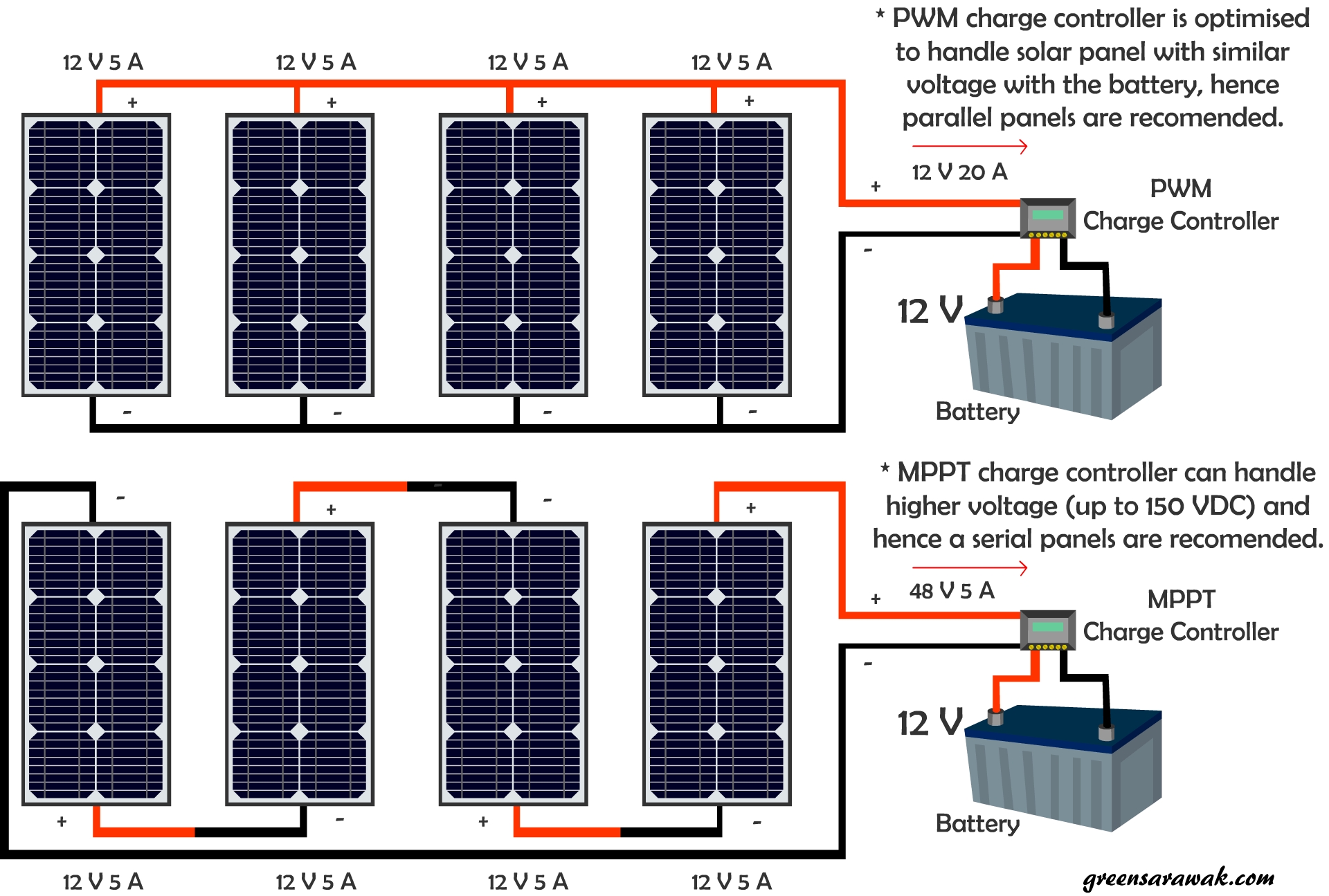
Types of solar charge controllers There are currently two types of charge controllers commonly used in PV power systems : 1. Pulse Width Modulation (PWM) controller 2. Maximum Power Point Tracking (MPPT) controller In this Instructable, I will explain to you about the PWM Solar Charge Controller.
Going Solar Chapter 14 Know Your Solar Charge Controller Green Sarawak
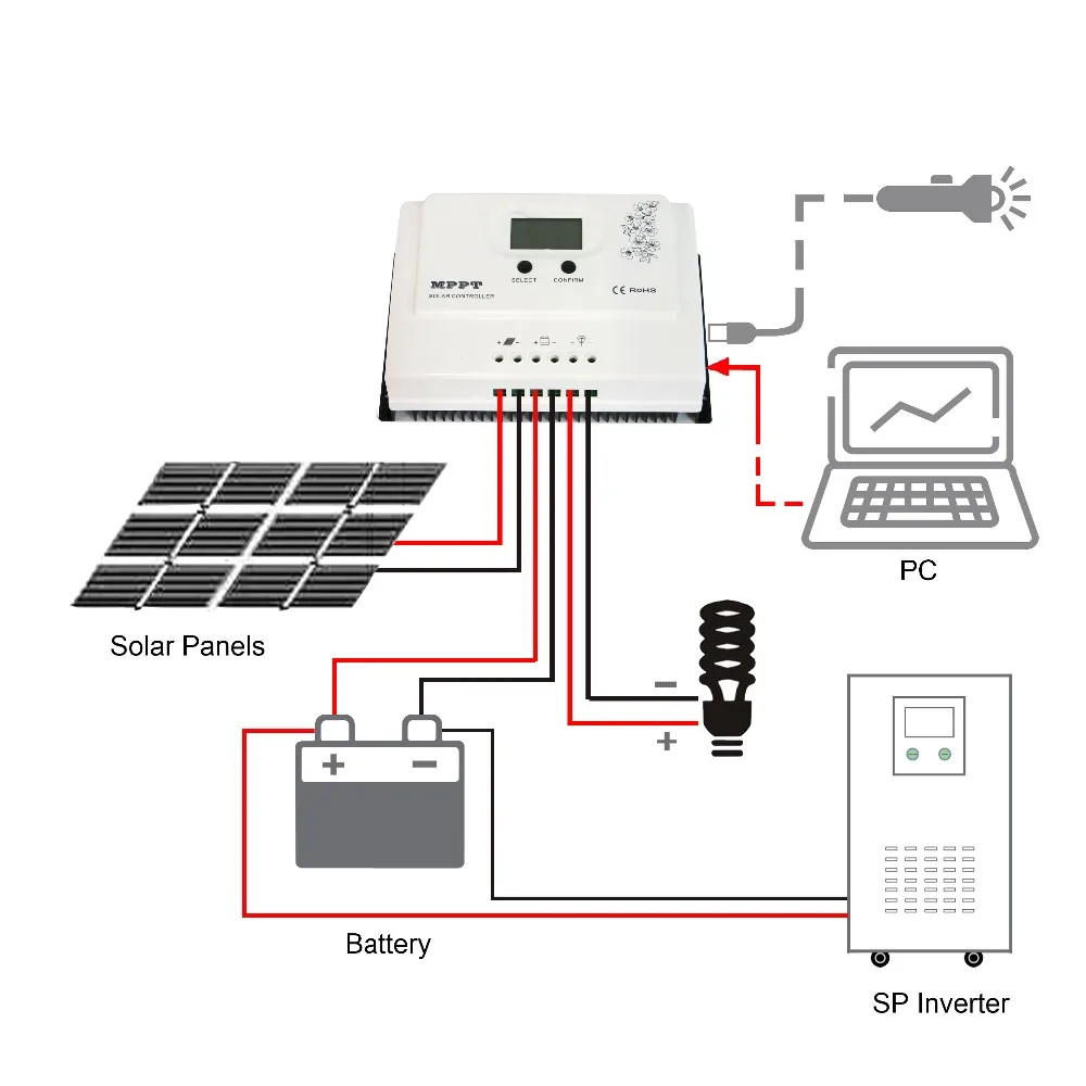
Step 1: Connect the Battery Note: Fire and explosion may occur if the positive and negative terminals of the battery are short-circuited. Make sure the battery voltage is higher than 6V if system is 12V, then start the controller before connecting the battery to the solar system.
Solar charge controller
The diagram below shows the working principle of the most basic solar charge and discharge controller. The system consists of PV module, battery, controller circuit and load. Switch 1 and Switch 2 are the charging switch and the discharging switch, respectively. When switch 1 is closed, the battery is charged by the PV module, and switch 1 also.
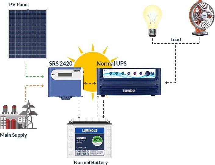
Solar Panel Wiring Diagram With Inverter
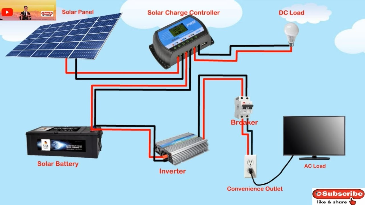
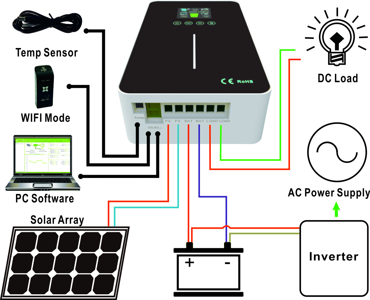
The first solar charge controller schematic below (Figure 1) illustrates how a solar charge controller is connected to power a direct current (DC) load, and the second one (Figure 2) pertains to an alternating current (AC) load. Figure1: Off-grid Diagram with DC Load
mppt solar charge controller schematic monitoring.solarquest.in
Diagram taken from my book off-grid solar power simplified. Unlike the PWM controller, an MPPT controller separates the array's voltage from the voltage of the battery. In other words, the solar system could have a 12V battery on the output of the MPPT charge controller and simultaneously have modules wired in series producing 36V on the input side.

MPPT XtraN Marine Solar Panel Charge Controller Marine Solar Panels
The post comprehensively explains nine best yet simple solar battery charger circuits using the IC LM338, transistors, MOSFET, buck converter, etc which can be built and installed even by a layman for charging all types of batteries and operating other related equipment Overview
Circuit Diagram Of Solar Charge Controller
Jan 2012 Wameedh Abdul-Adheem In this paper, we present a design and simulation of an efficient solar charge controller. This solar charge controller works with a PWM controlled DC-DC.
Mppt Solar Charge Controller Circuit Diagram Pdf
4.1 Parts list 4.2 Cost list Results and conclusions References Appendix A: Detailed Schematic Appendix B: Source code List of Figures Figure 1: MPPT and PWM graph Figure 2: MPPT performance match between the solar panel and the battery Figure 3: Solar charge block diagram solution Figure 4: Switch-Mode Charger Controller (BQ24650)
Cómo funciona el regulador solar MPPT
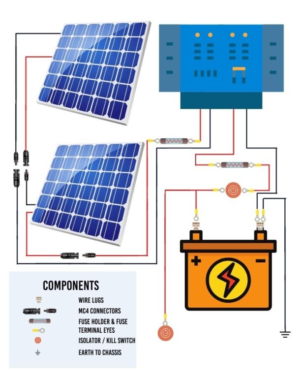
A standard solar panel charge controller wiring diagram includes the solar panels (PV Array), the charge controller, battery, and load. Each of these components is interconnected, with specific points of contact, as shown in the wiring diagram. Familiarize yourself with these diagrams and the specific make and model of your charge controller.
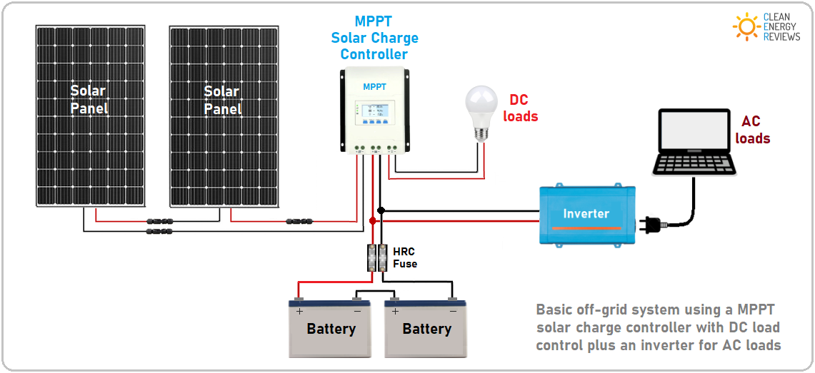
Best MPPT Solar Charge Controllers up to 40A — Clean Energy Reviews
Support & training TI E2E™ forums with technical support from TI engineers Content is provided "as is" by TI and community contributors and does not constitute TI specifications. See terms of use. . View the TI Solar charge controller block diagram, product recommendations, reference designs and start designing.

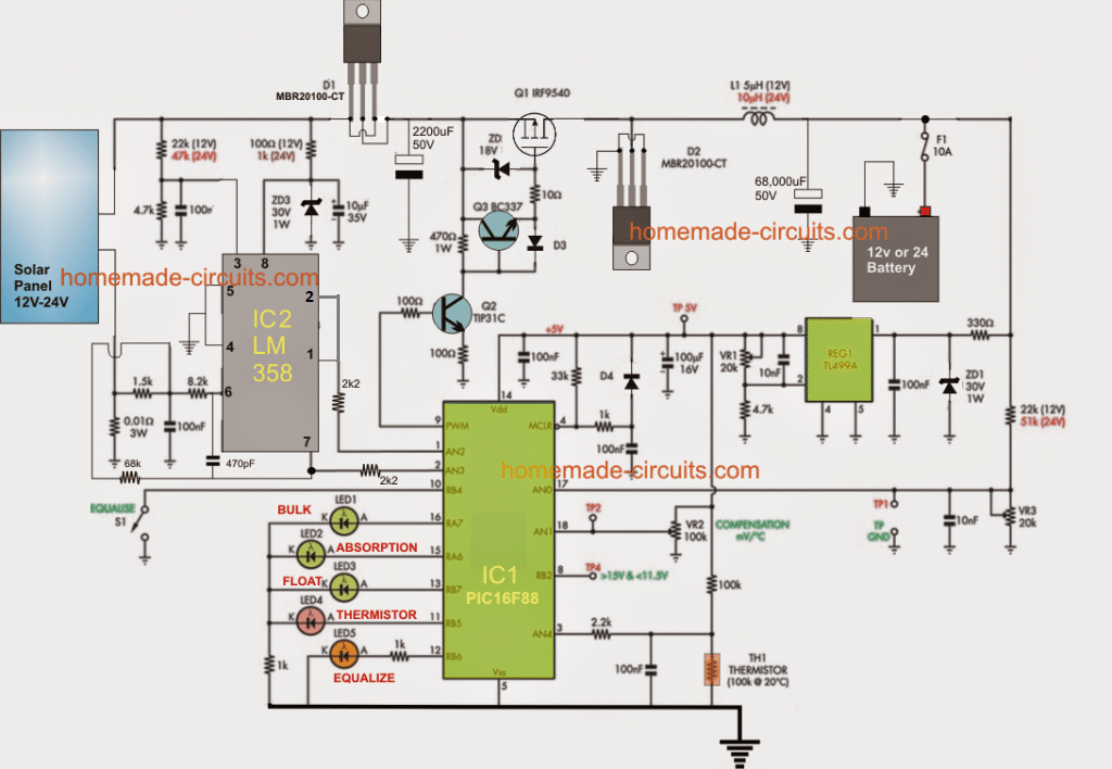
Figure10 Complete circuit diagram of a solar charge controller
A charge controller acts as a safety barrier between panels and a battery and should be a part of every home solar panel installation. In this article we'll explain how to wire together solar panels, a regulator and a battery. Charge controller keeps your battery safe But what does a battery fear? From what a controller actually protects it?

Getting started with solar power dxbard
Step 1: Connect the Battery to the Charge Controller Note: These installation instructions should not supersede those in your charge controller's or battery's manual. Where these instructions differ from your manual's, follow your manual! Check out the wiring diagram to see how to connect a solar panel to a charge controller:

5 Amp Solar Charger Controller Circuit
A DIY solar charge controller is a device that you can build yourself to regulate the voltage and current coming from your solar panels. It is used to maintain the proper charging voltage on the batteries, preventing overcharging and thus protecting your solar battery storage system.. Schematic Diagrams for Solar Charge Controller Build.
